Fluorescence Anisotropy/Fluorescence Polarization
The polarization of fluorescence radiation emitted by a sample is frequently correlated with the polarization of the exciting radiation. Usually the emitted radiation is parallel to the exciting radiation, but the degree to which it is not is a measure of randomization processes occurring inside the luminescing sample. Two parameters are often calculated to define the degree to which the light is randomized, P, or the fraction of light that is linearly polarized and r, the fluorescence anisotropy or that ratio of the polarized component to the total intensity.
![]()
![]()
Where I|| = the intensity of light parallel to the excitation
and I┴ = the intensity of light perpendicular to the excitation
In the following set up the polarization will remain linear and will “wag” between 0o and 90o (allowing equal dwell times into the sample cell).
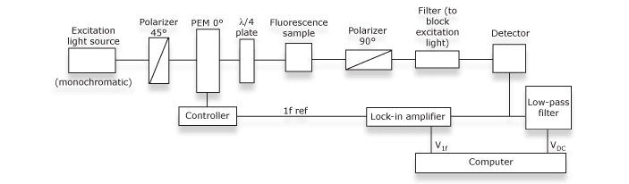
To get a value for fluorescence anisotropy one needs to measure the fluorescence intensity when the final (analyzing) polarizer is parallel to the exciting radiation (I|| ) and the intensity when the final polarizer is perpendicular to the exciting radiation (I┴). The waveform coming from the detector in this set up would be expected to look something like the sketch below: a small AC signal on top of a large DC signal.

Each of the peaks represents one extreme of the light polarization (0o or 90o), so the maximum should equal I|| and the minimum should equal I┴. The peak to peak AC voltage should be proportional to I|| – I┴. It is the root mean square (rms) AC voltage that is read by the lock in, but this can be converted (equation 3 below). The rms DC voltage can be read from the lock in or measured separately with a digital voltmeter. It is equal to the average of I|| + I┴.
So using the definitions:
![]() (1) Formula for degree of polarization
(1) Formula for degree of polarization
![]() (2) Formula for fluorescence anisotropy
(2) Formula for fluorescence anisotropy
And the fact that the rms signal is related to the peak to peak signal by:
![]() (3) Conversion of rms signal to peak-to-peak
(3) Conversion of rms signal to peak-to-peak
![]() (4) Degree of polarization in terms of lock in signals
(4) Degree of polarization in terms of lock in signals
![]() (5) Fluorescence anisotropy in terms of lock in signals
(5) Fluorescence anisotropy in terms of lock in signals
COMPANIES USING PEMS TO MEASURE FLUORESCENCE POLARIZATION:
FURTHER READING
Lakowicz, Joeseph R., Principles of Fluorescence Spectroscopy, Third Edition, Springer, New York, 2006
John E. Wampler and Richard J. DeSa, “Recording Polarization of Fluorescence Spectrometer – A Unique Application of Piezoelectric Birefringence Modulation”, Analytical Chemistry, 46, 563 (1974)
K.W. Hipps and G.A. Crosby, “Applications of the Photoelastic Modulator to Polarization Spectroscopy”, J. Phys. Chem 83, 555-562 (1979).
Contact us for information about using PEMs in Fluorescence – Luminescence applications.